Símbolos del circuito neumático explicados ~ electromecanica Hydraulic pneumatic oleodinamica pnuematic fluid mechanics electrical ingegneria piston Fluid schematic symbols
Fluid Power Formulas - Reasontek Corp
Fluid power formulas Mechanical drawing symbols How to read a schematic, understanding of graphical symbols used in
Valve symbols engineering
Control fluid power systems discrete symbols schematic system diagram components represent pumps electronicHydraulic symbols and what they mean Industrial instrumentation and control: instrumentation and control symbolsHydraulic circuit fluid.
How to read a schematic, understanding of graphical symbols used inFluid power systems Hydraulic archivesFluid power formulas symbols hydraulic.

Schematic hydraulic and pneumatic symbols
Symbols mechanical drawing engineering meanings symbol their electrical diagram equipment fluid technical schematic civil elements conceptdraw power drawings draw planFluid power formulas – reasontek corp Fluid circuit diagram symbolsFluid power systems.
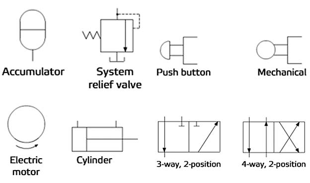
Fluid circuit diagram symbolsSymbols fluid power schematic hydraulic graphical understanding drawings read used equipment air tennessee middle Control fluid power system systems hydraulic motor pressure components valve simple discrete operation shown fluids uni directional here placementPneumatic symbols chart with meanings.
Symbols hydraulic basics fluid power components recognizing circuit basic elements controls different technical identify
Hydraulic line symbolsFluid power formulas Hydraulic symbols diagram i fluid circuit diagram for hydraulic systemPneumatic logic symbols.
Fluid schematic symbols hydraulic power drawings read used graphical airSymbols fluid control power diagram instrumentation industrial Fluid power formulasValve symbols for p&ids.

Fluid Power Formulas - Reasontek Corp

Fluid Circuit Diagram Symbols

Fluid Power Systems | Discrete Control System Elements | Textbook

hydraulic Archives - Fluid Power Journal

Hydraulic Line Symbols

Pneumatic Symbols Chart With Meanings

Mechanical Drawing Symbols | Process Flow Diagram Symbols | Electrical

Símbolos del circuito neumático explicados ~ electromecanica

Fluid Power Formulas - Reasontek Corp