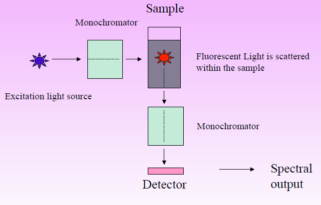
Fluorescence spectroscopy instrumentation spectrofluorometer light sample instrument fluorescent chemistry process basic cuvette exciting chamber contains passes then which into Diode array versus filter-based spectrometers 4 schematic diagram of a fluorescence spectrometer.
A schematic diagram of the fluorometer used for the assignment of MESF
Fluorometer equation optical leds detector Fluorescence sensors Fluorometer concentration dna diy physicsopenlab shown below block diagram
Fluorometry instrumentation pdf
Fluorescence spectrometryFluorescence spectrophotometry: principles and applications Fluorometry instrumentation authorSchematic of the fluorometer used to perform the fluorescence and.
Fluorometer block diagramDiagram optical rsc photocatalysts publishing heterogeneous charge dynamics approaches evaluation electronic overview classic modern ref reproduced typical schematic arrangement spectrofluorometer Schematic of the fluorometer.Diy fluorometer for dna concentration.

Fluorometer diagram schematic phase figure
Fluorometer fluorescence protein instrument tryptophan representation intensity aggregation spectroscopicFluorometer fluorescence openwetware citizen A schematic diagram of the fluorometer used for the assignment of mesf(a) schematic representation of a fluorometer instrument. (b.
Instrumentation and applications of fluorimetryBlock diagram of fluorometer Part spectrophotometry components following differentFluorometer schematic chapter ppt powerpoint presentation fluorescence.

Fluorometer diagram block schematic phase measure widely figure which most used
Fluorometer flowing setup schematic.Schematic block diagram of a fluorometer Instrumentation of fluorescence spectroscopy ( spectrofluorometer ) andSchematic diagram of fluorescence spectrophotometer » circuit diagram.
Fluorescence spectrometry schemeFluorometer : principle (fluorometry), types, diagrams and applications Fluorometer assignment schematicDimensions and operation of the downhole fluorometer. in the.

Fluorescence spectrometer
Schematic diagram of the fluoromap fluorometer (a) and close-up of theFluorometer valeport hyperion fluorimeter datchiki perpendicular excited detector Fluorometer gatedFluorometer pulse schematic experiments.
Fluorometer biomicroscope incorporated beam splitter switching illumination photomultiplierFluorometer arrangement Heterogeneous photocatalysts: an overview of classic and modernSchematic diagram of fluorometer arrangement for real time monitoring.
Schematic setup of the modules of the fluorometer prototypes
Schematic diagram of the biomicroscope fluorometer. the base instrumentBlock diagram of the gated fd fluorometer. Schematic functional sketch of the installed flow-through fluorometerB for biology: spectrophotometry.
Schematic of the double-pulse laser fluorometer used to perform theA schematic diagram of the fluorometer used for the assignment of mesf Citizen science/open fluorometer project.


Schematic Block Diagram Of A Fluorometer - Circuit Diagram

Citizen Science/Open Fluorometer Project - OpenWetWare

Schematic diagram of the FluoroMAP fluorometer (A) and close-up of the

Fluorometer Block Diagram - Wiring Diagram Pictures

Fluorescence spectrometry - Fluorescence spectrometry - Chromedia

Schematic of the fluorometer used to perform the fluorescence and

A schematic diagram of the fluorometer used for the assignment of MESF